Line Following Robot Kit Build: Selecting Motors and Chassis Kits
A line following robot kit build is the classic entry point into robotics for kids. The concept is simple: the robot follows a black line on a white surface using infrared sensors. This guide takes you through selecting the right motors and chassis, placing the IR sensors, debugging the code, and building a race track to test speed. Even a complete beginner can complete a line following robot kit build in a weekend.
Selecting Motors and Chassis Kits
The foundation of a successful line following robot kit build is the drive train.
Motors: DC gear motors with a nominal speed of 150–200 RPM work best. Faster motors make the robot overshoot the line. Choose motors with a 3V–6V rating that run quietly and include rubber wheels for grip. Common choices are the N20 micro metal gearmotors or standard TT yellow gear motors.
Chassis: You can buy a pre‑cut acrylic chassis kit for $10–15, or design one using LEGO Technic bricks. Many line following robot kit build tutorials use the “2‑wheel drive + caster wheel” configuration because it’s stable and turns easily.
Motor driver: An L298N or MX1508 motor driver module receives control signals from the Arduino or ESP32 and delivers power to the motors.
Pairing two N20 motors with a small ABS chassis and an L298N creates a nimble robot perfect for this line following robot kit build.
IR Sensor Placement and Calibration
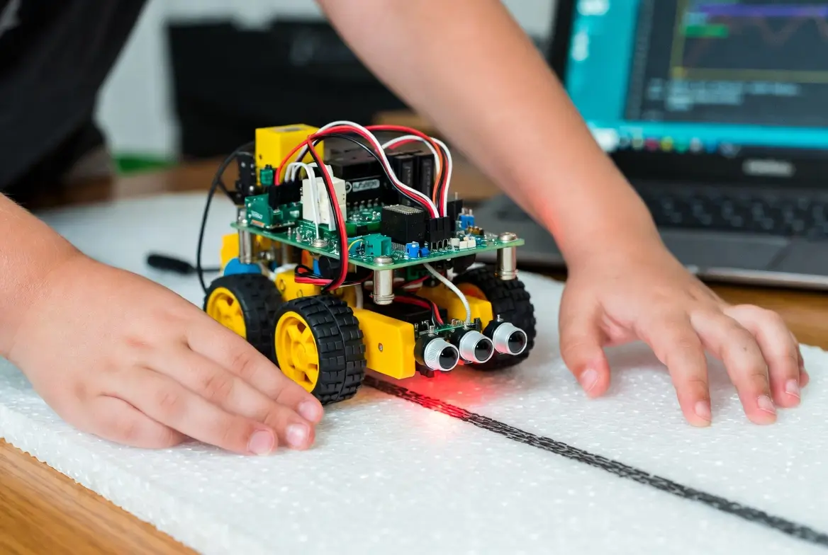
Infrared sensors are the eyes of your line following robot kit build. Typically, an array of 3 to 5 IR sensor modules (like the popular TCRT5000) is mounted on the front underside.
- Spacing: Space the sensors slightly less than the line width so at least one sensor is always above the line.
- Calibration: Each sensor will output an analog value that changes depending on whether it’s over black or white. Wire the sensors to analog inputs on the microcontroller. In the code, read all sensors, determine the threshold between black and white, and compute a “line position” (a value from –100 to 100) that tells the robot whether the line is centered or offset to the left/right.
Accurate calibration is the secret behind every reliable line following robot kit build.
Debugging Code Loops
The control loop in a line following robot kit build follows a PID (Proportional‑Integral‑Derivative) logic, but beginners can start with a simple proportional controller.
Pseudocode:
text
line_error = line_position - center
motor_speed = base_speed - (Kp * line_error)
left_motor = base_speed + motor_speed
right_motor = base_speed - motor_speed
- If
Kpis too high, the robot wobbles aggressively. - If too low, it reacts sluggishly and falls off the line.
- Tune
Kpby increasing it until the robot just begins to oscillate, then back down slightly.
Print the sensor values to the serial monitor to understand what the robot sees. Most line following robot kit build problems are solved by tightening sensor wiring or adjusting the threshold.
Race Track Ideas to Test Speed
Once your line following robot kit build is stable, build a track to test performance.
- Materials: Black electrical tape on a white foam board, or large sheets of paper with a printed black curve.
- Design: Start with a simple oval. Add a crossover, 90‑degree turns, and a chicane to test responsiveness.
- Challenge: Time the robot over a fixed distance. Use the timer to measure improvements as you tune
Kpvalues or increase the base speed. - Competition: Organise a race with friends. The fastest line following robot kit build that stays on the line wins.
Building the track is half the fun and gives immediate feedback on every code change.
A line following robot kit build teaches mechanics, electronics, and coding all in one project. By the end of the weekend, your child (and you) will have built a robot that can think for itself, following a line wherever it leads.