DIY Home Energy Monitor: Know Exactly Where Your Watts Go
A diy home energy monitor can reveal that your old fridge is costing you $30 a month, or that your “standby” electronics are sucking power 24/7. Using a non‑invasive CT clamp sensor clipped around your main power wire, an ESP32 reads current and calculates real‑time energy consumption, then sends the data to Home Assistant or a simple web dashboard. No electrician needed, and you never touch a live wire. Here’s how to build your own diy home energy monitor in an afternoon.
How a CT Clamp Sensor Works
The heart of any diy home energy monitor is the Current Transformer (CT) clamp. It’s a plastic‑cased ring that opens and clips around one of the live wires feeding your house. Inside the clamp, a coil picks up the magnetic field generated by the alternating current flowing through the wire. This field induces a tiny current in the clamp, proportional to the load. A small circuit (often built into the sensor, or using a burden resistor on the ADC input of the ESP32) converts that into a voltage the microcontroller can read. The key advantage: you never break the circuit or expose any bare conductor. For a diy home energy monitor, the SCT‑013‑030 (30A) or SCT‑013‑000 (100A) clamp is the standard choice just be sure to match the amp rating to your main breaker.
Wiring the ESP32 and CT Clamp
For your diy home energy monitor, you’ll need:
- ESP32 dev board (any variant)
- SCT‑013 CT clamp sensor
- A 3.5 mm audio jack breakout (the clamp terminates in a headphone‑style plug)
- A 10 µF capacitor (optional, for filtering)
- A USB power supply
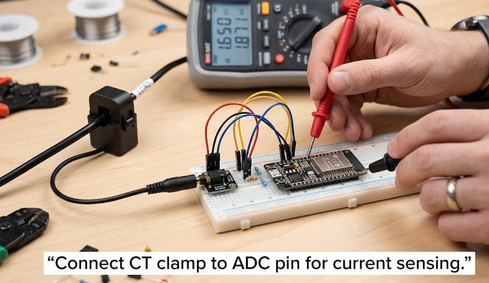
The SCT‑013 outputs a small AC voltage (typically 0‑1V). The ESP32’s ADC reads 0‑1V as a default, but it’s not perfectly linear at the edges. Wire the jack’s tip to GPIO34 (ADC1 channel), sleeve to GND. Add a 10 µF capacitor between the ADC pin and GND to smooth noise. In ESPHome (the easiest route for Home Assistant), you configure an adc sensor with a ct_clamp platform that applies a scaling factor to convert raw ADC readings into amps. For a split‑phase main panel, use two clamps on each hot leg, and sum the power.
Integrating with Home Assistant & ESPHome
A diy home energy monitor really shines inside Home Assistant, where you can set up the Energy dashboard. After flashing ESPHome to your ESP32, add this to the YAML:
sensor:
  - platform: ct_clamp
    sensor: adc_sensor
    name: "House Current"
    update_interval: 10s
    filters:
      - calibrate_linear:
          - 0 -> 0
          - 0.005 -> 12.5
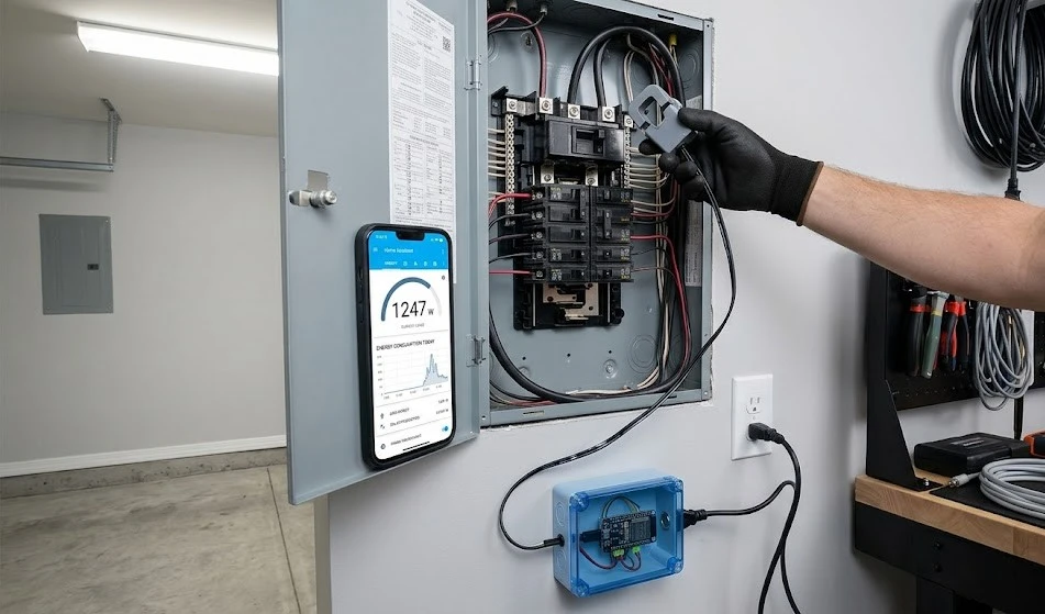
The linear calibration maps the ADC voltage to actual current. You’ll calibrate by comparing the reading to a known load (a 100W bulb, for instance). Once current is accurate, multiply by mains voltage (assumed 120V or 230V) to get watts, then integrate over time for kWh. Home Assistant’s Energy configuration will pick up these entities and display daily, weekly, and monthly graphs. This is the moment your diy home energy monitor becomes genuinely useful you can see exactly which hours are most expensive and which appliances are the culprits.
Spotting Power Hogs and Lowering Your Bill
With your diy home energy monitor running for a week, you’ll notice patterns. The baseline load at night (router, fridge, chargers) might be 100‑200 watts. When the dryer kicks on, it jumps to 3000 watts. Now you can act: swap old incandescent bulbs for LEDs, put entertainment centres on a smart power strip that cuts power when the TV is off, or replace that ancient garage freezer. Many users report savings of 10‑20% simply by identifying and eliminating idle loads. The beauty of a diy home energy monitor is that it pays for itself within a few months the parts cost under $20.